Gitarrförstärkare
Introduction
DIY Guitar amp from AL160 Altec Lansing Subwoofer
Maker: Håkan Walterson
Kostnad: 10 kr.
Status: Klart, ca. 100-200 timmars jobb
The project is a DIY (do it yourself) project, making use of old junk and other things I had saved.
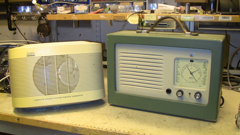
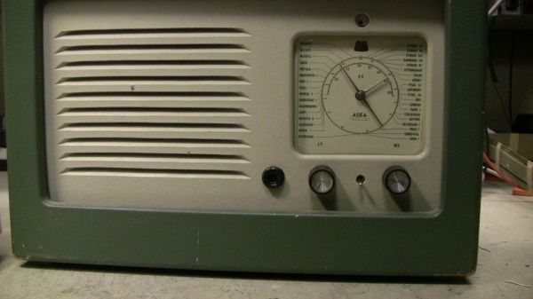
It started with the chassis of an old traveler’s radio from 1953, and with the Altec Lansing subwoofer saved from the scrap heap when the management closed down the Uppsala branch of the company where I work.
The idea was to do reverse engineering on the subwoofer and convert it into a guitar amp, and to use the old radio as the housing.
The main components of the subwoofer are the standard IC KIA324 (LM324) 4 x Op amp, a compressor circuit (NE572) and the KIA 6210 stereo power amp, and of course the twin coil Altec Lansing 6" Speaker. When I had downloaded the power amp data sheet I discovered that each channel contained two bridge coupled power amps, which is a common car stereo design to get high power from low power supply voltage (2 x 22 W at 14V), and with max voltage 20V. Promising...
Implementation
Reverse Engineering and preliminary design
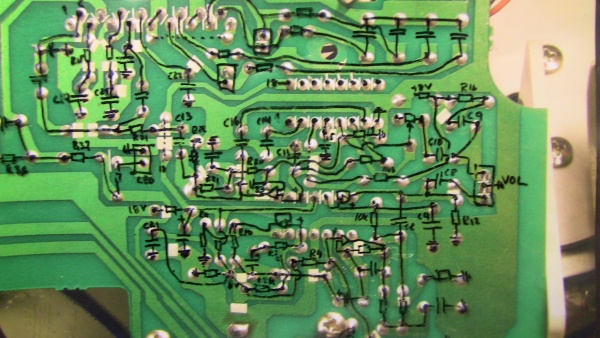
After some preliminary tries the first serious reverse engineering step was to take photos of the front and backside of the printed circuit board. With the help of the free software Inverted Image I inverted the backside photo so that it would be easier to trace the circuit diagram. And with the help of the enlarged photos it was fairly easy to get a complete diagram. I put the photo inside a plastic folder, and drew the PCB lines on the plastic (see below). From the front side photo I could identify the components, which I drew as ordinary electronic symbols on the plastic folder.
gitarrforstarkare_rev_engineering_pcb_on_film.pdf This is the original reverse engineering work. Enlarged photos of the front and back of the PCB with schematics drawn on a plastic folder tracing the PCB copper layout. The pdf shows the schematics without the PCB board.
The schematics showed that there was one preamp stage with a low pass filter (consisting of two OP amps), then a third order low pass filter, a compressor stage made up of the fourth op amp and the KIA power amp. The signal was fed to both channels of the power amp, and each output was connected to its own loudspeaker coil. I suppose that when the company name is Altec Lansing it is easy to manufacture a speaker with two coils so that you can use a stereo power amp. I have not included the complete original schematics here for the simple reason that I have mistakenly thrown it in the waste basket…
After some removal and bypassing of the low pass filters I made a try to keep the compressor, but I did not get any significant effect, so I removed the compressor circuit.
At that stage the amplifier worked, the input stage was fixed, and one op amp was remade into a V/2 reference. The power supply provided one single voltage (14 V) and the original V/2 source was a simple voltage divider with a capacitor.
The second op amp sourced the volume pot, and then the last op amp upped the gain a little.
The circuit board photo, at some time at the start of the project when I realized it was too difficult to do reverse engineering without good visuals. Some tests had been made, e.g. bypassing the low pass filter part and increasing the input impedance to a more fitting 500k. On top the power amp with a low budget Aluminum L-profile heat sink
The tone control
Now the amp needed a tone control. I had decided to try and use the tuning mechanics of the radio, and the first try was to build a Fender tone stack, and replace one of the capacitors with the tuning capacitor. This did not work at all, too much hum and no good performance. Another drawback was that the tone stack designs required three controls on the front, which would alter the minimalistic look too much. I searched the Internet, and of course I found the perfect design, i. e. the tone control of the classic distortion pedal Big Muff Pi. The first source I found was Big Muff Design. Thanks a lot.
Frequency response with the “Fender” characteristic
Frequency response with the “Marshall” characteristic
White – max bass
Blue – 15 % up
Yellow – mid position (50%)
Cyan – max treble
The differences between the Marshall and the Fender tone stacks inspired me to add a switch to be able to change the characteristics of the Big Muff circuit.
With the help of the Tone Stack Calc 1.3 application, which provided the Big Muff frequency response curves for different component values it was easy to add the changeable “Marshall/Fender” switch that increases low mid for the Marshall sound.
Now I had something that worked fine, and it was also possible to replace the tuning capacitor in the radio with the 50k mixer potentiometer in the Big Muff tone control. The only difficult thing was to drill the 2,5 mm hole in the axle and then make a thread with the M3 thread tool.
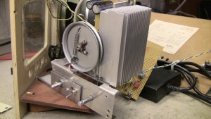
When I had mounted the potentiometer on a L profile and fixed it to the radio chassis I could use the old tuning dial to get the high precision tone control (where every city name gives a different tone).
Two pictures showing the tone control utilizing the original frequency wheel, now attached to the 50k pot.
The Built In Stomp Boxes
When I told my son in law (who is in the Gypsy Punk music business as a singer in Crash Nomada) about my project he told me that he had an original Big Muff stomp box, and we spent an evening looking at schematics on the Internet. I thought it would be fun to add the Big Muff distortion to the amp. It consists of two transistor stages with diode voltage limiters providing a very high distortion effect. When I described the project to a friend of mine, he revealed the he was the owner of the first version of the Ibanez Tubescreamer. Electrosmash.com provided schematics and with the addition of two diodes and a gain potentiometer to the input stage the Tubescreamer was there.
To get a little more output power I decided to try and use a Laptop power supply. The Dell 90 W supply has a stabilized voltage of 19,2 V. which raises the output power to 2 x 35 W. I tried other Dell supplys but they induced hum and noise. The 90W supply is silent. It also has the advantage off short circuit protection, and has high efficiency. So the ring transformer of the Altec Lancing was left out.
The original heat sink (Aluminum L-profile) was replaced with a heat sink I had salvaged when I scrapped an old Dell computer.
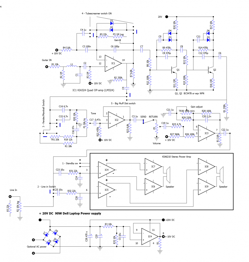
The Complete Design
The component numbering is made by the DIYLC-3.28 Circuit drawing program (https://code.google.com/p/diy-layout-creator/w/list , recommended) and does not correspond to the PCB numbering.
Some notes: Components that does not do any harm has been kept on the board, e.g. L1. All diodes are 1N4148.
The input stage also makes up the Tubescreamer circuit. Since there is no total bypass, I excluded the Tubescreamer input buffer stage. The Tubescreamer switch turns on the diode circuit and switches off C4 to get the high pass filter cutoff at 720 Hz. (R4 & C3 connected to IC1.). In normal position the high pass frequency is 72 Hz. Gain is adjustable roughly from 10 to 100 times which is sufficient for normal guitar pick ups. The roll off frequency provided by C6 and R5-R6 is lowered as the gain is increased to get a softer clipping.
The Big Muff distortion stages (the two transistor stages) are implemented with original component values. I have actually a PCB switch to be able to select only the first Big Muff stage. As you can see the Tubescreamer and Big Muff can be turned on simultaneously, but without noticeable effect. Big muff has already turned everything into a square wave.
The Tone control is an adaption of the Big Muff circuit, with a switch that can change characteristics in a nice way. The reason for using the 50k pot is simply because I had one with a 6 mm axle that made it possible to drill the hole for the screw in the center of the frequency dial.
The Buffer stage and the last preamp stage is nothing special. Gain is adjustable, but that is only because the original board had a trim pot. The output of the buffer stage can be tapped off as echo send and return.
I could not resist the temptation of separating the stereo output stages to enable two signal sources. The additional input jack is placed on the backside of the amplifier. The input level can be adjusted with a pot and is the put directly in one of the power stages.
On the speaker outputs I have jacks so that I can connect external speakers and disconnect the internal speaker (or use one external and one coil of the internal speaker).
The Hardware
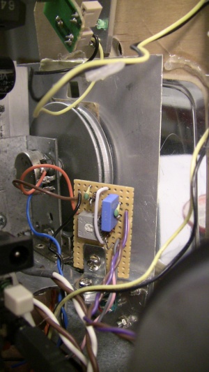
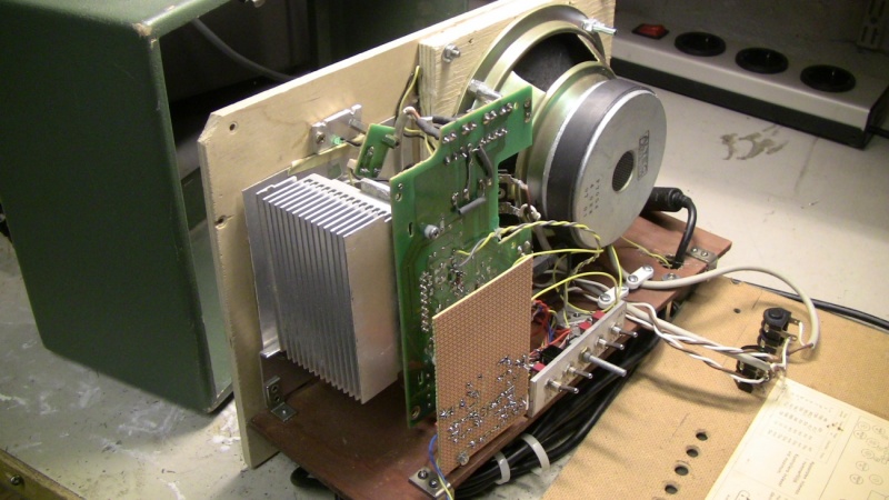
The main parts: Computer heat sink, Altec subwoofer printed circuit board, The new Veroboard with the distortion circuits, Altec loudspeaker. Note the extra baffle in front of the loudspeaker.
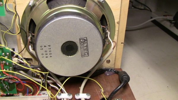
The original Altec Lansing speaker with its two coils.
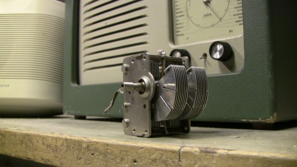
The original tuning capacitor of the radio
Two additional holes had to be drilled for the guitar input and the Fender/Marshall switch. The switch has later switched place with the gain pot
Result
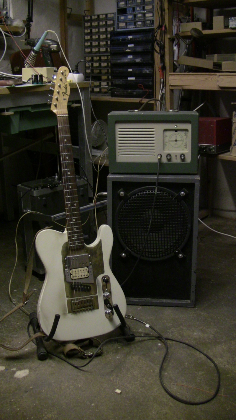
The ASEA Guitar Amplifier with my old Telecaster. The Black Shadow loudspeaker works well if you want more output.
